How Lithium Batteries Charge: CC/CV, the TP4056 Module and Protection Circuits
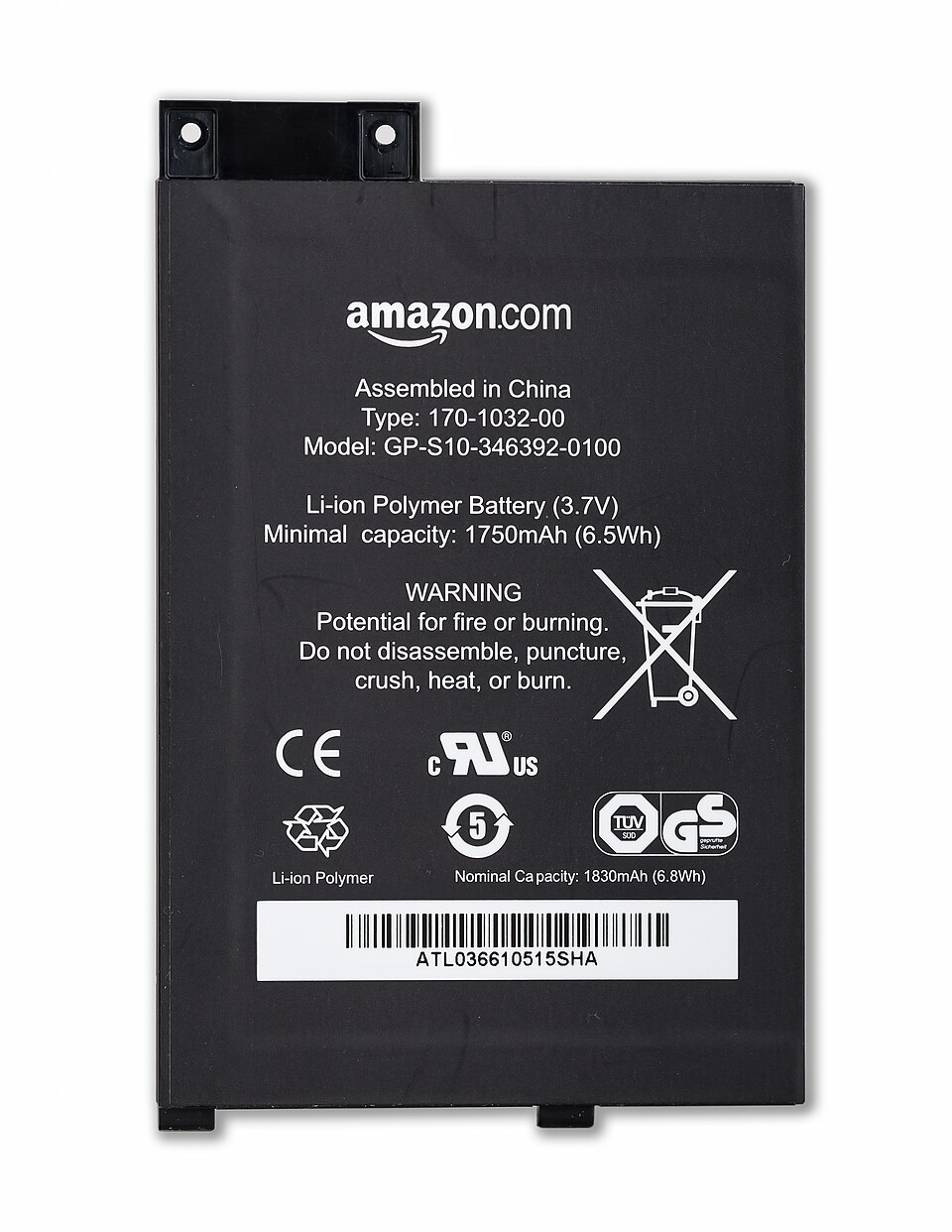
Every LiPo and 18650 in your projects charges the same way: constant current, then constant voltage. Learn what the TP4056 module actually does, how to set its charge current safely for small batteries, and what the protection chip on the back is for.
Lithium cells power almost every portable project we build: line-following robots, the MicroMouse, handheld games and wireless sensor nodes. They store a lot of energy in a small space, which is exactly why they need to be charged correctly. This article explains the charging process, the cheap TP4056 module that most hobbyists use, and the protection circuitry that makes it safe.
This covers single-cell lithium-ion and lithium-polymer cells (3.7 V nominal, 4.2 V full) such as 18650s and pouch LiPos. LiFePO4 and multi-cell packs use different voltages and chargers.
The two phases: CC then CV
A lithium-ion cell charges in two stages:
1. Constant Current (CC). The charger pushes a fixed current into the cell, and the cell's voltage rises steadily from about 3.0–3.7 V toward 4.2 V. Most of the capacity goes in during this phase.
2. Constant Voltage (CV). When the cell reaches 4.2 V, the charger stops raising the voltage and holds it at exactly 4.2 V. The current now tapers off naturally as the cell fills up.
Termination: charging stops when the current has fallen to a small fraction of the CC current. The TP4056 ends the charge at one tenth of the programmed current (C/10). After that, the charger doesn't keep "topping up". Lithium cells don't tolerate continuous trickle charging the way NiMH cells do.
Battery University's guide on charging lithium-ion explains why the 4.2 V limit is strict. Typical cells allow only about ±50 mV of tolerance. Pushing beyond it increases capacity slightly, but stresses the cell and shortens its life, and at worst it's a safety hazard. Many long-life applications deliberately charge to a lower voltage, around 4.1 V, and accept a bit less capacity.
There's often a third, preliminary phase too: if the cell is deeply discharged (below about 2.9 V for the TP4056), the charger first applies a small trickle current until the voltage recovers, then starts the full CC phase.
How fast? The C-rate
Charge current is described relative to capacity. 1C for a 1000 mAh cell is 1000 mA, and 0.5C is 500 mA. For most consumer cells, the datasheet's standard charge rate is around 0.5C, with 1C as a common maximum. Faster than that generates heat and accelerates wear. Always check the cell's datasheet: small pouch cells sometimes specify lower rates.
The TP4056 module
The blue TP4056 board is the default single-cell charger in hobby electronics. The chip:
- performs CC/CV charging with a fixed 4.2 V target,
- sets the charge current with one resistor, RPROG,
- terminates at C/10 and restarts automatically if the cell later drops (around 4.0 V),
- drives two LEDs: charging, and done.
Setting the charge current
The TP4056 datasheet gives a table relating RPROG to charge current:
| RPROG | Charge current |
|---|---|
| 10 kΩ | 130 mA |
| 5 kΩ | 250 mA |
| 3 kΩ | 400 mA |
| 2 kΩ | 580 mA |
| 1.5 kΩ | 780 mA |
| 1.2 kΩ | 1000 mA |
Here's the trap: most modules ship with 1.2 kΩ, which means 1 A. That's fine for a 2000–3000 mAh 18650. It's 2C for a 500 mAh LiPo, and 5C for the 200 mAh cells used in small wearables. For small batteries, swap the RPROG resistor, a tiny SMD part near the chip, usually marked "122". A 500 mAh cell at about 0.5C wants roughly 250 mA, so use 5 kΩ.
The TP4056 is a linear charger. The difference between the 5 V USB input and the battery voltage is burned as heat. At 1 A with the cell at 3.7 V, that's about 1.3 W in a tiny chip, so the board gets hot. The chip reduces the current automatically if it overheats, so slow charging on a hot board is expected.
Protection: the second chip on the board
Look for modules labelled "with protection". They have two extra parts: a DW01A protection IC and a dual MOSFET (often FS8205A). Together they disconnect the battery if:
- it's over-charged (above about 4.3 V),
- it's over-discharged (below about 2.4 V),
- too much current is drawn, or the output is shorted.
On these boards, B+ / B− go to the cell, and OUT+ / OUT− go to your circuit. If you connect your circuit straight to B+/B−, you bypass the protection.
Over-discharge protection matters a lot for robots. A motor left running will drain the cell far below its safe minimum, and a lithium cell taken that low can be permanently damaged. Many 18650 cells are sold "protected", with a small protection board built into the cell. Pouch LiPos from RC hobby suppliers usually aren't.
Multi-cell packs need balancing
A TP4056 charges one cell (or several cells in parallel, which behave like one big cell). Two cells in series, a 2S pack like the 7.4 V pack in a typical robot, cannot be charged from a single-cell charger. Use a proper 2S charger with balancing. A balance charger watches each cell individually so that one cell doesn't end up over-charged while the other is still low. If your robot runs on two 3.7 V cells in series, as many line-followers do, charge them as a balanced 2S pack, or charge each cell separately with its own single-cell charger.
Safety habits
- Never charge a swollen ("puffy") pouch cell. Swelling means internal damage. Retire it safely.
- Don't charge below 0 °C, and avoid charging hot cells.
- Don't leave cheap chargers unattended for hours on flammable surfaces, especially with unknown cells.
- Insulate the terminals. A shorted LiPo can deliver enormous current instantly. Tape exposed tabs and use connectors that can't be reversed.
- Check polarity before connecting. Many TP4056 boards have no reverse-polarity protection on the battery side.
Watch it happen
Our cinematic lesson How Batteries Charge — CC / CV / BMS animates the CC and CV phases and the protection circuit step by step. Batteries and regulators are also covered on Day 5 of the ElectroLab course.
References
- Battery University, BU-409: Charging Lithium-ion: batteryuniversity.com
- NanJing Top Power ASIC, TP4056 Datasheet (RPROG table, termination): dlnmh9ip6v2uc.cloudfront.net
- Fortune Semiconductor, DW01A One-Cell Lithium-ion/Polymer Battery Protection IC: datasheet (PDF)