Voltage Dividers for Sensors and ADCs: A Practical Guide
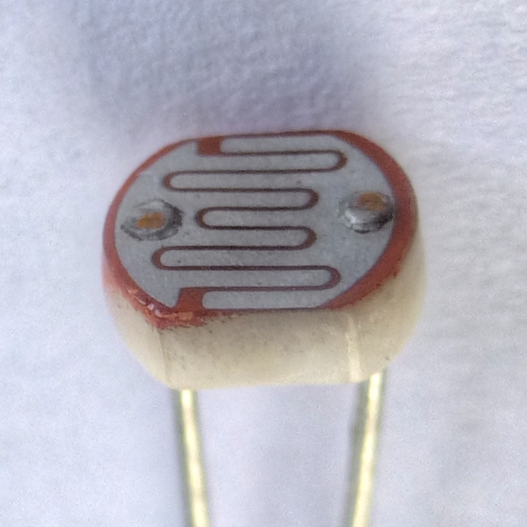
Two resistors turn a voltage into a smaller one. Learn the voltage divider formula, how to read an LDR or potentiometer, how to measure a LiPo battery with an ESP32, and the loading mistake that makes dividers give wrong readings.
A voltage divider is two resistors in series. It's one of the most used circuits in hobby electronics, and also one of the most misused. It's perfect for measuring things and almost always wrong for powering things. This guide covers both sides.
The formula
Connect R1 from the input voltage to a middle point, and R2 from that middle point to ground. The voltage at the middle is:
Vout = Vin × R2 ÷ (R1 + R2)
The intuition: the same current flows through both resistors, so each one drops a share of the voltage proportional to its resistance. Equal resistors split the voltage in half. If R2 is three times R1, Vout is three quarters of Vin.
Example: 5 V in, R1 = 10 kΩ, R2 = 10 kΩ → Vout = 5 × 10 / 20 = 2.5 V.
Use 1: reading resistive sensors
Microcontrollers can't measure resistance directly, but their ADC (analog-to-digital converter) can measure voltage. A divider converts one into the other.
LDR (light-dependent resistor): put the LDR as R1 and a fixed resistor as R2. As light increases, the LDR's resistance drops, and Vout rises. A good fixed value is roughly the LDR's resistance at the light level you care about most. For many common LDRs, 10 kΩ is a sensible start. This is exactly how the light-seeking and line-sensing circuits on Day 4 of the ElectroLab course work.
Potentiometer: a potentiometer is a voltage divider. Its two outer pins are the ends of a resistive track and the wiper is the middle point. Connect the outer pins to 3.3 V and GND and the wiper to an ADC pin, and turning the knob sweeps the reading from 0 to full scale.
Thermistor (NTC): same idea, but the resistance falls as temperature rises, and the relationship isn't linear. Use the Steinhart–Hart equation or the B-parameter equation from the datasheet to convert the reading to temperature.
Use 2: measuring a battery
Say you want an ESP32 to report the voltage of a 2-cell LiPo pack, which ranges from about 6.0 V empty to 8.4 V full. The ESP32's ADC pins must never exceed 3.3 V, and in practice the ADC is most accurate well below that.
Choose a ratio of 1:4. With R1 = 30 kΩ and R2 = 10 kΩ: Vout = 8.4 × 10 / 40 = 2.1 V at full charge, and 1.5 V when empty.
That sits comfortably inside the range where the ESP32's ADC is reasonably linear. With the default 11 dB attenuation, Espressif's guidance puts the most accurate region at roughly 0.15–2.45 V. In firmware, multiply the reading by 4 to get the battery voltage back. Then calibrate against a multimeter: ±5% resistors and ADC error can add up to a few percent.
Current drawn by the divider: 8.4 V / 40 kΩ ≈ 0.21 mA, always flowing. For a battery-powered device that sleeps for weeks, use higher values (for example 300 kΩ / 100 kΩ) or switch the divider off with a MOSFET when you aren't measuring.
Use 3: 5 V → 3.3 V signal shifting
A 5 V sensor output into a 3.3 V ESP32 pin can damage it. A divider with R1 = 1 kΩ and R2 = 2 kΩ gives 5 × 2/3 ≈ 3.33 V. That's fine for slow, one-directional signals, such as an HC-SR04 ultrasonic sensor's ECHO pin.
It's not fine for fast or bidirectional buses like I²C. The resistors and the pin capacitance slow down the edges, and the divider only works in one direction. Use a proper level-shifter module there.
The mistake: loading the divider
The formula assumes nothing draws current from the middle point. As soon as something does, that load appears in parallel with R2, the effective R2 drops, and Vout sags.
Example: a 10 kΩ / 10 kΩ divider from 9 V should give 4.5 V. Connect a load that behaves like 1 kΩ to the output, and the bottom becomes 10 kΩ ∥ 1 kΩ ≈ 909 Ω. Vout collapses to about 9 × 909 / 10 909 ≈ 0.75 V.
This is why a voltage divider is not a power supply. You cannot run a 3.3 V module from 5 V through two resistors. The module's current draw changes constantly, so its voltage would swing all over the place. Use a voltage regulator (a linear LDO, or a buck converter for efficiency). Regulators are covered on Day 5 of the course.
For measurement, loading is small but still real. An ADC input looks like a high resistance plus a small sampling capacitor that needs charging. Two practical rules:
- Keep the divider's output impedance moderate. The ATmega328P datasheet recommends a source impedance of about 10 kΩ or less for its ADC. The output impedance of a divider is R1 ∥ R2.
- For high-value dividers, add a capacitor (100 nF is typical) from the ADC pin to ground. It acts as a local reservoir that charges the sampling capacitor and filters noise. The trade-off is slower response, which doesn't matter for a battery voltage that changes over minutes.
Choosing resistor values
- Pick the ratio from the maximum input and the voltage you want at maximum.
- Pick the scale. Lower values (1–10 kΩ) are stiffer and less noisy but waste more current. Higher values (100 kΩ+) save power but are more sensitive to loading and noise.
- Round to standard values and recompute the real ratio.
- Use ±1% resistors if accuracy matters.
- Check the worst case: at the highest possible input, is Vout still below the pin's maximum?
Try it
The free Voltage Divider calculator computes the output for any pair of resistors and helps you pick values for a target ratio. To see a divider respond to a changing input, build one with a potentiometer in the circuit sandbox.
References
- Espressif, ESP-IDF Programming Guide — ADC (attenuation and calibration): docs.espressif.com
- Microchip, ATmega328P Datasheet, Analog-to-Digital Converter section: microchip.com
- SparkFun, Voltage Dividers: learn.sparkfun.com