Build a Line-Following Robot: From Two IR Sensors to PID Control
The line follower is the classic first robot. Build it in two stages: a simple two-sensor version that works in an afternoon, then an 8-sensor PID version that's smooth and fast — with a step-by-step method for tuning the gains.
A line-following robot reads a black line on a white floor (or the reverse) and steers to stay on it. It's the classic first robot because it combines everything at a manageable scale: sensors, a microcontroller, motor drivers, power, and a control loop. It also leads straight into competition robotics. Our MicroMouse is a line follower with a maze-solving brain on top.
We'll build it in two stages: a simple version you can get working in an afternoon, then the version that's actually fast.
Parts
- Chassis: two driven wheels plus a caster. A two-wheel differential-drive kit works fine.
- Motors: small geared DC motors (N20s for a compact robot, or yellow TT motors for a beginner kit)
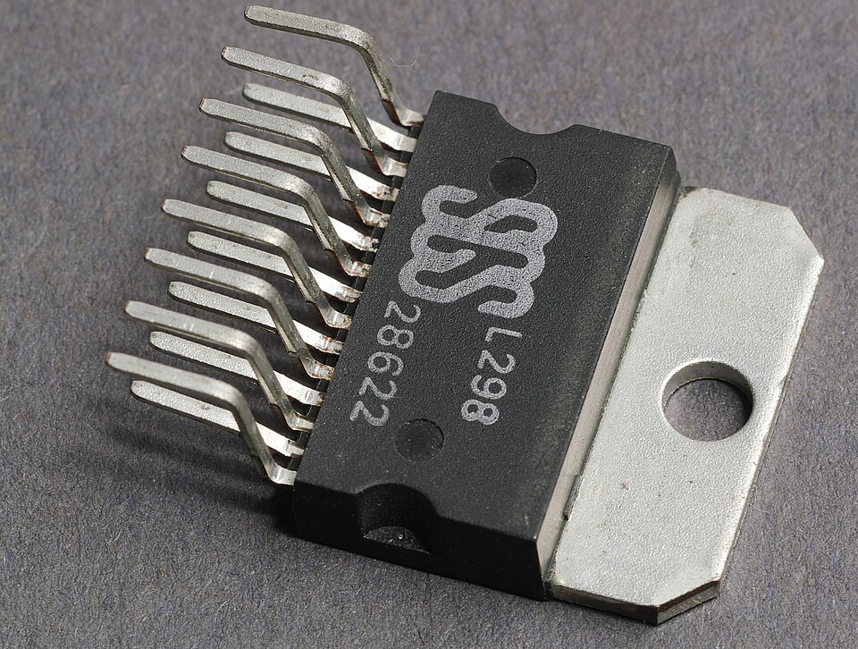
- Motor driver: an L298N module, L293D, or TB6612FNG. The TB6612FNG wastes much less voltage, which matters on small batteries.
- Controller: Arduino Uno or Nano (an ESP32 works too)
- Sensors: stage 1 uses two IR reflectance modules (TCRT5000-type). Stage 2 uses an 8-sensor array such as Pololu's QTR-8A/8RC.
- Power: a 2-cell Li-ion/LiPo pack (7.4 V) or 6×AA, with the logic powered from a regulator. Charging is covered in How Lithium Batteries Charge.
How the sensors see the line
Each IR sensor has an infrared LED and a phototransistor side by side. White surfaces reflect a lot of IR and black surfaces absorb it, so the phototransistor's output changes with what's underneath. Distance matters a lot: Pololu specifies an optimal sensing distance of about 3 mm for the QTR-8RC, with about 9.5 mm as the maximum recommended. Mount the sensors low and level.
The cheap single-sensor modules usually have a comparator and a potentiometer on board, so they output a digital HIGH/LOW. Adjust the potentiometer until the module's LED changes state exactly at the edge of the line.
Stage 1: two sensors, bang-bang control
Place two sensors either side of the line, both on white when the robot is centred.
| Left sensor | Right sensor | Meaning | Action |
|---|---|---|---|
| White | White | Centred | Drive straight |
| Black | White | Drifted right | Turn left |
| White | Black | Drifted left | Turn right |
| Black | Black | Junction or stop line | Stop (or decide) |
void loop() {
  bool leftOnLine  = digitalRead(LEFT_SENSOR)  == LINE_DETECTED;
  bool rightOnLine = digitalRead(RIGHT_SENSOR) == LINE_DETECTED;

  if (!leftOnLine && !rightOnLine)      drive(150, 150);  // straight
  else if (leftOnLine && !rightOnLine)  drive(60, 150);   // steer left
  else if (!leftOnLine && rightOnLine)  drive(150, 60);   // steer right
  else                                  drive(0, 0);      // both: stop
}
Whether LINE_DETECTED is HIGH or LOW depends on your module, so check with the serial monitor first.
This works, but watch it run. The robot zig-zags because it only knows "left", "right" or "centred", and always corrects by the same amount. Speed it up and it overshoots and loses the line. That's the limit of bang-bang control.
Stage 2: eight sensors and a position estimate
With an array of eight sensors, you can estimate where the line is, not just which side it's on. Pololu's QTR library calculates a weighted average: with 8 sensors it returns 0 when the line is under the first sensor, 7000 under the last, and 3500 when centred, with every value in between.
Now the error is a number with a size, not just a direction:
int position = qtr.readLineBlack(sensorValues);
int error = 3500 - position;  // 0 = centred; sign = which side; size = how far
PID control in plain terms
A PID controller turns that error into a steering correction:
correction = Kp × error + Ki × (sum of errors) + Kd × (change in error)
- P (proportional): steer harder the further you are from the line. This does most of the work.
- D (derivative): react to how fast the error is changing. If the robot is swinging back toward the centre quickly, D eases off the correction early, which stops overshoot. It's the damping.
- I (integral): corrects a persistent offset. Most line followers set Ki = 0, making them PD controllers, because the integral term winds up through sharp turns and causes overshoot.
Apply the correction as a speed difference between the wheels:
int correction = Kp * error + Kd * (error - lastError);
lastError = error;

int left  = constrain(BASE_SPEED + correction, 0, MAX_SPEED);
int right = constrain(BASE_SPEED - correction, 0, MAX_SPEED);
drive(left, right);
If the robot steers away from the line, swap the signs, or swap which side gets +.
Calibrate first
Before reading positions, run the library's calibration while sweeping the sensors across the line, so it learns each sensor's minimum (white) and maximum (black). Our MicroMouse does this automatically by rotating left and right on the spot for about a second at power-up. Calibrate on the real track under the real lighting.
Tuning the gains, step by step
There's no formula for Kp and Kd. They depend on your robot's weight, motors, wheel size, sensor position and speed. Use this procedure:
- Start slow. Pick a modest base speed. Set Kp and Kd to 0.
- Increase Kp until the robot follows the line but oscillates (wobbles) side to side. Note that value.
- Add Kd, gradually, until the oscillation dies out and the robot runs smoothly. Kd is often several times larger than Kp, because the change in error per loop is small.
- Raise the base speed, then repeat steps 2–3. Higher speeds usually need more Kd.
- Keep the loop timing constant. The D term depends on the time between loops. If you add
Serial.print()calls or delays later, the tuning changes.
Symptoms and causes:
| Symptom | Likely cause |
|---|---|
| Slow, lazy wobble; cuts corners and drifts off | Kp too low |
| Fast, tight oscillation | Kp too high, or Kd too low |
| Smooth on straights, flies off sharp turns | Base speed too high for the curve; reduce speed or increase Kp |
| Jittery, twitchy motors | Kd too high, or noisy sensor readings |
For reference only, the team's MicroMouse v2 used Kp = 0.151 and Kd = 0.8 at full PWM. Your values will be different, but notice how much larger Kd is.
Common problems
- The robot works on the bench but not on the track: recalibrate under the track's lighting, and check the sensor height.
- One motor is faster than the other: normal for cheap motors. PID compensates on curves, but you can also add a small fixed offset to one side.
- The Arduino resets when the motors start: the motors are pulling the battery voltage down. Power the logic from a separate regulator, add a large capacitor (470 µF or more) across the motor supply, and make sure all grounds are connected.
- It's slow even at full PWM: the L298N drops roughly 2 V or more internally. Switching to a MOSFET-based driver like the TB6612FNG gives the motors more of the battery voltage.
Going further
Once your robot follows lines reliably, the next step is maze solving: detecting junctions, exploring with the left-hand rule, and replaying the shortest route. That's covered in How Our MicroMouse Solves a Line Maze. The sensors, motor drivers and a line-following robot build are also on Day 4 of the ElectroLab course, and PID control on Day 5.
References
- Pololu, QTR-8A and QTR-8RC Reflectance Sensor Array User's Guide: pololu.com
- Pololu, QTR Sensors Arduino Library (readLine and calibration): github.com/pololu/qtr-sensors-arduino
- Brett Beauregard, Improving the Beginner's PID: brettbeauregard.com
- STMicroelectronics, L298 Dual Full-Bridge Driver datasheet: st.com