Using a Transistor as a Switch: Drive Relays, Motors and LED Strips from a Microcontroller
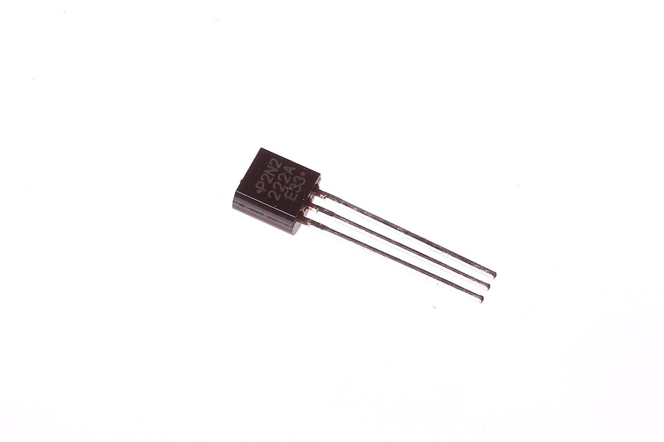
A microcontroller pin can light an LED, but not a relay, motor or LED strip. Learn how to switch bigger loads with an NPN transistor or a logic-level MOSFET, how to calculate the base resistor, and why the flyback diode is not optional.
A GPIO pin is a signal, not a power source. It can supply a few milliamps at 3.3 V or 5 V, which is enough for an LED and nowhere near enough for a relay coil, a motor or a strip of LEDs. The standard answer is to let the pin control a transistor, and let the transistor switch the load from a proper supply.
This guide covers the low-side NPN switch, which every beginner should be able to draw from memory, then the MOSFET version, and the diode that keeps inductive loads from killing your transistor.
The idea in one sentence
A small current into the transistor's control terminal lets a much larger current flow through its main path. The microcontroller supplies the small current, and a separate supply provides the big one.
The low-side NPN switch
For an NPN bipolar transistor (such as the BC547 or 2N2222):
- Emitter → ground
- Collector → the load's negative side
- Load's positive side → the supply (5 V, 12 V, or whatever the load needs)
- Base → the GPIO pin, through a base resistor
It's called "low-side" because the transistor sits between the load and ground. When the pin goes HIGH, current flows into the base, the transistor turns on, and the load is connected to ground. When the pin goes LOW, the load switches off.
Grounds must be shared. The microcontroller's GND and the load supply's GND must be connected. Without a common reference, the base current has no return path and the switch doesn't work. This is the most common wiring fault we see in workshops.
Calculating the base resistor
To use a bipolar transistor as a switch, you drive it into saturation: fully on, with only a small voltage (a few tenths of a volt) across collector-emitter. Designers make sure of this by supplying more base current than the bare minimum. A common rule is to aim for a forced gain of about 10–20: IB ≈ IC / 10.
Example: a 5 V relay from an ESP32.
- Find the load current. Check the relay's coil rating. Common 5 V "sugar-cube" relays draw roughly 70–90 mA. We'll use 80 mA.
- Pick the transistor. A BC547 is rated for 100 mA collector current, which is too close for comfort. A 2N2222 is rated for 600 mA, which is comfortable.
- Base current: IB = 80 mA / 10 = 8 mA.
- Base resistor: the base-emitter junction drops about 0.7 V, so RB = (3.3 − 0.7) / 0.008 ≈ 325 Ω, giving 330 Ω.
8 mA is within what an ESP32 pin can supply, but it's not tiny. For heavier loads, a MOSFET is the better choice.
The flyback diode
Relay coils, solenoids and motors are inductors. An inductor resists changes in current. When the transistor switches off suddenly, the coil tries to keep the current flowing, and the only way it can do that is by generating a large voltage spike, easily tens of volts, across the transistor. Repeat that enough times and the transistor fails, often taking the microcontroller with it through noise on the supply.
Fix: put a diode across the coil, reverse-biased in normal operation. The cathode (the striped end) goes to the positive supply side and the anode to the transistor side. When the transistor switches off, the coil's current circulates harmlessly through the diode and decays.
- A 1N4007 or 1N4148 is fine for small relays.
- Many relay modules already include the diode and the transistor. Bare relays don't.
- For DC motors driven in both directions, use an H-bridge driver with built-in protection instead, such as the L293D, TB6612FNG, or modules like the L298N covered on Day 4.
When to use a MOSFET instead
An N-channel MOSFET does the same low-side job, but it's controlled by voltage at the gate, not current. Once switched, the gate draws essentially no steady current. This makes MOSFETs better for higher currents: LED strips, motors, heaters.
The catch is picking a logic-level MOSFET that fully turns on at your microcontroller's voltage:
- Look at the datasheet's RDS(on) (on-resistance) specification and the gate voltage it's specified at. If RDS(on) is only given at VGS = 10 V, the part won't fully switch on from a 3.3 V pin.
- VGS(th) (threshold voltage) is not the turn-on voltage. It's the point where the MOSFET starts to conduct a tiny current. A 2 V threshold doesn't mean it works well at 3.3 V.
- For 3.3 V logic, small parts such as the AO3400 (RDS(on) specified at VGS = 2.5 V) are a popular choice. For 5 V logic, the IRLZ44N family is common.
A typical MOSFET low-side switch uses:
- a gate resistor of about 100 Ω in series with the GPIO, to limit the inrush current into the gate capacitance, and
- a pull-down resistor of about 100 kΩ from gate to ground, so the MOSFET stays off while the microcontroller is resetting and its pins are floating. See pull-up and pull-down resistors.
The flyback diode rule applies to MOSFETs too.
Checking power dissipation
Even a "fully on" switch dissipates some power:
- BJT: P ≈ VCE(sat) × IC. At 0.3 V and 80 mA, that's 24 mW. Fine.
- MOSFET: P = I² × RDS(on). At 3 A and 0.05 Ω, that's 0.45 W. A small SOT-23 package will get hot, so check the datasheet's thermal limits or choose a larger package.
If the transistor is too hot to touch, it's either not fully switched on (check the gate or base drive) or undersized for the load.
PWM through a transistor
The same circuit dims LEDs and controls motor speed with PWM (pulse-width modulation). The GPIO switches the transistor on and off rapidly, and the load sees an average power proportional to the duty cycle. MOSFETs handle PWM well. At high PWM frequencies, the gate's capacitance makes the switching edges slower, which is when you'd add a dedicated gate driver. For hobby frequencies of a few kHz, a direct GPIO drive is usually fine.
Try it
Transistors as switches, including how they build logic gates, are animated on Day 2 of the ElectroLab course. Motors and H-bridge drivers come up on Day 4, and relays with flyback diodes on Day 5. You can wire a transistor switch virtually in the sandbox.
References
- onsemi, P2N2222A Datasheet (collector current, saturation voltage): onsemi.com
- Alpha & Omega Semiconductor, AO3400A Datasheet: aosmd.com
- SparkFun, Transistors tutorial (switching applications): learn.sparkfun.com
- Texas Instruments, L293x Quadruple Half-H Drivers datasheet: ti.com