How to Use a Multimeter: Voltage, Current, Resistance and Continuity
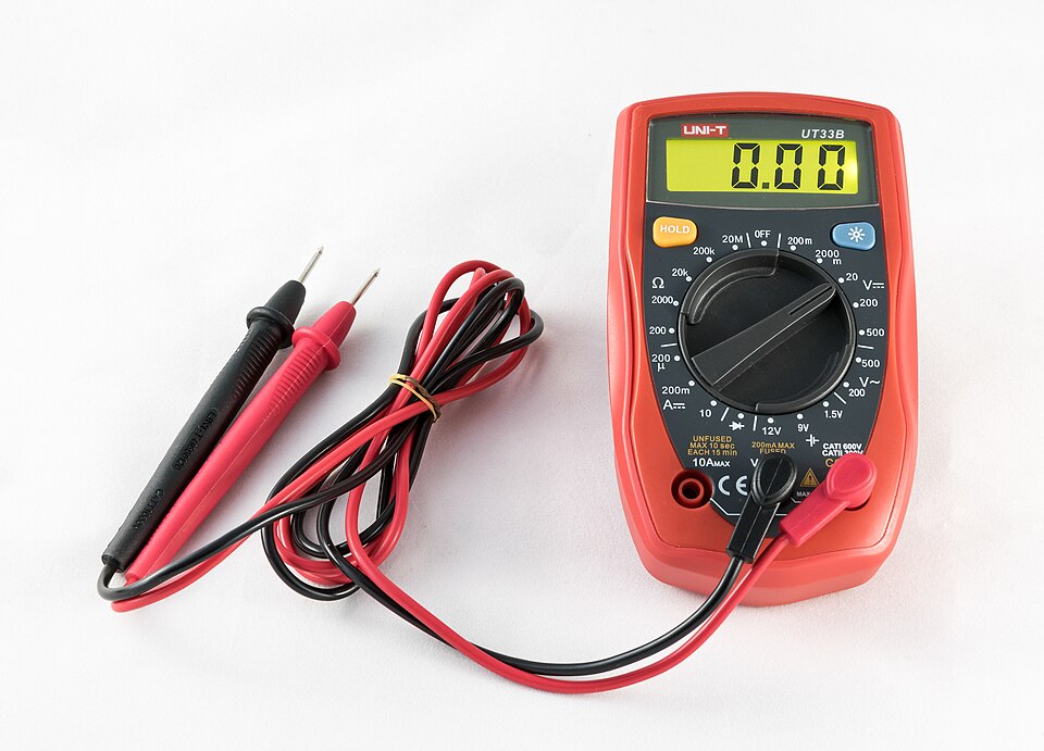
A multimeter is the first tool to buy and the one you'll use most. Learn how to measure voltage, current and resistance, use continuity mode to debug a PCB, and avoid the mistake that blows the meter's fuse.
When a circuit doesn't work, guessing wastes hours. A multimeter replaces guessing with numbers. In our workshops it's the tool we hand out first, and the one that solves most "it's not working" questions within a minute. A basic digital meter is cheap, and it's enough for nearly everything in hobby electronics.
The parts of a meter
- Dial (rotary switch): chooses what you measure. Common positions are V⎓ (DC voltage), V~ (AC voltage), Ω (resistance), the diode/continuity symbol, and A⎓ / mA (DC current).
- Jacks: almost every meter has a COM jack (black probe, always), a VΩ jack (red probe, for most measurements), and one or two current jacks (often 10 A and mA/µA).
- Auto-ranging vs manual: an auto-ranging meter picks the scale for you. On a manual meter you choose a range such as 20 V. Start higher than you expect and step down.
The rule that prevents most accidents: the black probe stays in COM. The red probe stays in VΩ, except when you are deliberately measuring current.
Measuring DC voltage
Voltage is measured across something, with the meter in parallel.
- Set the dial to V⎓.
- Black probe to ground (or the lower-voltage point), red probe to the point you're testing.
- Read the value. A negative sign just means the probes are reversed.
What to check first on a dead circuit:
- Supply at the source. Is the battery or adapter actually giving its rated voltage?
- Supply at the chip. Measure directly between the IC's VCC and GND pins. A broken breadboard rail or a bad solder joint shows up here.
- Logic levels. A digital pin should read close to 0 V or close to VCC (3.3 V or 5 V). Something in between often means a floating input. See pull-up and pull-down resistors.
Safety note: these steps are for low-voltage circuits (batteries, USB, bench supplies). Mains voltage needs a properly CAT-rated meter, training, and a different set of precautions. Don't learn on mains.
Measuring resistance
- Turn the circuit off. The meter measures resistance by passing its own small current. External voltage gives garbage readings and can damage the meter.
- Set the dial to Ω.
- Touch the probes to each end of the component.
Measuring in-circuit is unreliable because other parts in parallel change the result. To verify a value properly, lift one leg or measure before soldering. Our resistor colour code guide explains how to read the value from the bands first.
Continuity mode: the debugging superpower
Continuity mode (the speaker or sound-wave symbol) beeps when the resistance between the probes is very low. You can probe a board without looking at the screen. Use it to:
- Check for shorts after soldering. Probe between VCC and GND before applying power. A continuous beep means a solder bridge or a wrong connection. This single check has saved a lot of boards at our PCB fabrication workshops.
- Verify traces and wires. Does this header pin really connect to that IC pin? On home-etched PCBs, hairline cracks in traces are common and invisible.
- Find broken jumper wires. Cheap Dupont jumpers fail internally more often than you'd think.
Note: a large capacitor between the two points may beep briefly while it charges. That's not a short. A real short beeps continuously.
Diode test
In diode mode, the meter shows the forward voltage of a diode or LED junction: about 0.5–0.7 V for a silicon diode, and often enough to make an LED glow faintly. Reverse the probes and it should read open (OL). This is a quick way to find an LED's polarity, check a diode, or test a transistor's base-emitter junction.
Measuring current, carefully
Current is measured through something. The meter must be in series, so you break the circuit and let the current flow through the meter.
- Move the red probe to the current jack. Use mA for small currents and 10 A for large ones. If you're unsure, start on 10 A.
- Set the dial to the matching current range.
- Break the circuit (for example, disconnect the supply wire) and connect the meter across the gap, so the current has to flow through it.
- Read, then move the red probe back to VΩ immediately.
Why that last step matters: in current mode, the meter is a near-zero-resistance path, essentially a short circuit. Leave the probe in the current jack, then try to "measure voltage" across a battery, and you short the battery through the meter. Best case, the internal fuse blows. Worst case, with a large battery and a cheap meter, things get hot. This is the most common way beginners break meters.
A safer trick: measure the voltage across a known resistor in the circuit, then use Ohm's law: I = V/R. No circuit-breaking, no fuse risk. See Ohm's Law Made Simple.
A debugging routine that works
When a project doesn't work, go in this order:
- Power off. Continuity between VCC and GND. No beep means no short.
- Power on. Voltage at the supply, then at each chip's power pins.
- Signals. Voltage on the input and output pins you care about. Do they change when you press the button or cover the sensor?
- Components. If one stage looks wrong, power off and check its parts' values and connections.
Nine times out of ten, the fault turns up in steps 1 or 2.
Try it
Using a multimeter is taught on Day 1 of the ElectroLab course, alongside the breadboard. The component library explains the parts you'll be measuring.
References
- SparkFun, How to Use a Multimeter: learn.sparkfun.com
- Fluke, What is a Digital Multimeter?: fluke.com
- Fluke, Electrical safety articles (measurement categories and safe practice): fluke.com