How to Choose an LED Resistor (and Why Your LED Needs One)
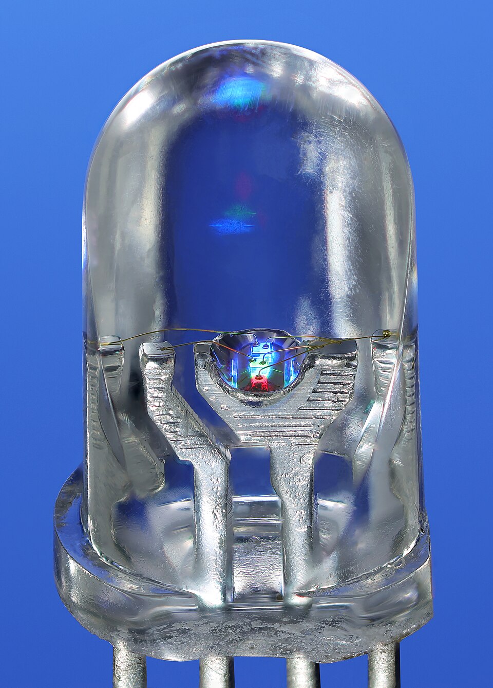
An LED without a resistor is a short circuit with a light on it. Learn the one formula for sizing an LED resistor, typical forward voltages by colour, safe pin currents for Arduino and ESP32, and how to wire several LEDs correctly.
The first circuit most people build is an LED and a resistor. The first component most people destroy is an LED without one. This guide explains why the resistor is there, how to calculate its value in one line, and the details that change when you move from a 5 V Arduino Uno to a 3.3 V ESP32.
Why an LED needs a resistor
A resistor obeys Ohm's law: double the voltage and you double the current. An LED doesn't. Below its forward voltage (Vf), almost no current flows. Just above it, current rises extremely steeply. A tiny increase in voltage, or a little heating of the LED, can multiply the current several times over.
So you can't simply "give the LED the right voltage". You have to limit the current. A series resistor does this: whatever voltage is left over after the LED's forward drop appears across the resistor, and Ohm's law then fixes the current.
The formula
R = (Vsupply − Vf) ÷ ILED
- Vsupply — the voltage driving the LED (5 V from an Uno pin, 3.3 V from an ESP32 pin)
- Vf — the LED's forward voltage (from the datasheet, or the table below)
- ILED — the current you want, in amps
Then round up to the next standard resistor value.
Typical forward voltages
These vary by manufacturer and current, so treat them as starting points and check the datasheet if you have one:
| LED colour | Typical Vf |
|---|---|
| Red | 1.8 – 2.2 V |
| Orange / yellow | 2.0 – 2.2 V |
| Yellow-green (older type) | 2.0 – 2.4 V |
| True green, blue, white | 2.8 – 3.4 V |
The split comes from the semiconductor material. Red and yellow LEDs use materials with a smaller bandgap than blue, white and true-green ones.
Worked examples
Red LED from an Arduino Uno pin (5 V), aiming for about 15 mA: R = (5 − 2.0) / 0.015 = 200 Ω, so choose 220 Ω. Actual current: (5 − 2.0) / 220 ≈ 13.6 mA. That's bright and well within the pin's limits.
Blue LED from an ESP32 pin (3.3 V), aiming for 5 mA: R = (3.3 − 3.0) / 0.005 = 60 Ω, so choose 68 Ω. The catch: you only have 0.3 V of headroom. Because blue LED forward voltages vary from part to part, the brightness will vary a lot between LEDs, and some may barely light. For blue and white LEDs on 3.3 V, it's often better to switch them from 5 V with a transistor.
Power in the resistor (first example): P = (5 − 2.0) × 0.0136 ≈ 0.04 W. A standard ¼ W resistor is fine.
How much current is enough?
Many indicator LEDs are rated for 20 mA continuous, but modern LEDs are very efficient. 2–10 mA is plenty for an indicator that you look at directly, and it's easier on the microcontroller. In our workshops, 330 Ω to 1 kΩ on a 5 V pin gives a clearly visible LED with a very low current.
Microcontroller pin limits
The microcontroller pin is part of the circuit too, and it has limits:
- ATmega328P (Arduino Uno/Nano): the datasheet lists 40 mA per pin as the absolute maximum. That's a damage threshold, not an operating point. Stay at or below about 20 mA per pin, and watch the total current for the whole chip.
- ESP32: the datasheet gives 40 mA maximum per GPIO, and a much lower total budget across all pins. Pin voltage also sags noticeably under load. For anything over a few mA, or many LEDs at once, use a transistor or a driver.
As a practical rule: direct from a pin is fine for one or two indicator LEDs. For LED strips, high-power LEDs or more than a handful of LEDs, use a transistor, a MOSFET, or a dedicated LED driver.
Wiring multiple LEDs
In series (one resistor, LEDs end to end): subtract every LED's forward voltage. R = (Vsupply − n × Vf) ÷ I. Three red LEDs on 9 V at 15 mA: (9 − 6) / 0.015 = 200 Ω, so choose 220 Ω. If n × Vf is close to or above the supply voltage, the LEDs won't light.
In parallel, with one resistor per LED. This is the correct way to run several LEDs from a low voltage. Each LED gets its own resistor, so each one's current is set independently.
Don't share one resistor between parallel LEDs. The LED with the slightly lowest forward voltage will take most of the current, run hot, and fail. Then the next one takes it all, and so on. Forward voltages differ between parts even from the same bag.
Common mistakes
- LED in backwards. The longer leg is the anode (+). The flat edge on the rim and the shorter leg mark the cathode (−). A reversed LED simply doesn't light, which is harmless at these voltages, but it's the most common "my circuit doesn't work" in workshops.
- Resistor on the "wrong" side. It doesn't matter. In a series circuit, the resistor works the same before or after the LED.
- Using a 10 kΩ by mistake. The LED will be extremely dim. Brown-black-orange (10 kΩ) and brown-black-red (1 kΩ) are easy to confuse under warm light.
Try it
Our free LED resistor calculator does this calculation and picks the nearest standard value for you. Resistors are covered on Day 1 of the ElectroLab course and the LED resistor calculation on Day 4, and you can wire one virtually in the circuit sandbox.
References
- Microchip, ATmega328P Datasheet, Electrical Characteristics: microchip.com
- Espressif, ESP32 Series Datasheet, DC characteristics: espressif.com
- SparkFun, Light-Emitting Diodes (LEDs): learn.sparkfun.com